3 Wire Infrared Detector Wiring Diagram / When the ir sensor circuit is switched on, ir led starts emitting the infrared, which falls upon the photodiode and a potential difference is generated across photo diode which turns on the transistor bc547, which.
3 Wire Infrared Detector Wiring Diagram / When the ir sensor circuit is switched on, ir led starts emitting the infrared, which falls upon the photodiode and a potential difference is generated across photo diode which turns on the transistor bc547, which.. The circuit diagram of the ir sensor using transistors namely obstacle detection using two transistors is shown below. New addressable fire alarm wiring diagram smoke detector webtor. This is my first instructables hope so it would be goodwe are gonna make a simple ir detector. Although nationwide 3 wire proximity sensor wiring diagram wiring laws can be found,specified additional prerequisites may be important and required to adjust to wiring restrictions. It is wired as shown in the figure.
The infrared detectors are specified for different sensitivities. Different ir leds may produce infrared light of differing wavelengths, just like different leds the ir rays from the ir led in the circuit are shown in the camera. Radar detector circuit diagram elegant radar detector user manual. Best ways to wire for a pir sensor, wiring diagram for motion detectors, where to motion detector positioning. Ir (infrared) detector circuit diagram.
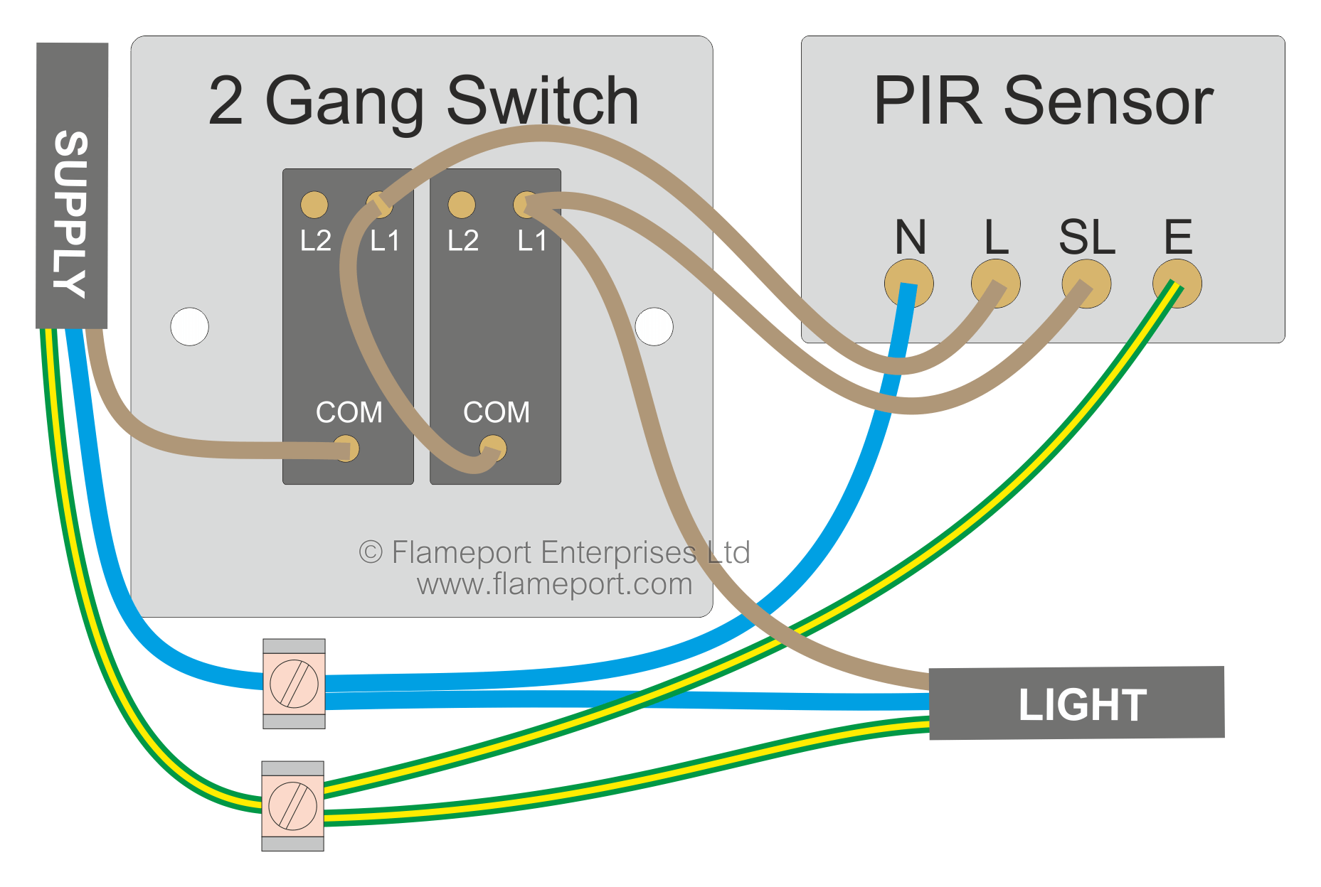
Motion Sensor Wiring With Switched Override Feature from www.flameport.com A passive ir detector is most. For more infrared detectors check the list bellow. This is the simple proximity detector circuit diagram. Infrared detector can be used in various equipment such as burglar alarms, touch free proximity switches for turning on a light. Improved infrared detector circuit scheminfra atic, using with commercial infra red remote control the infrared detector circuit may be powered by just about any standard 9v compact battery or a wall adaptor little laser trip wire circuit presented here can detect movement of people or objects wh. This proximity detector using an infrared detector (fig. New addressable fire alarm wiring diagram smoke detector webtor. If the target temperature exceeds the sensitivity specified, the output of the detector will be diagram 1 a:
An infrared detector is simply a transducer of radiant energy, converting radiant energy in the infrared into a first generation linear arrays were usually frontside illuminated, with the detector signal output connected by wire bonding to each element in the array.
The output from astable is fed to an. For more infrared detectors check the list bellow. Infra red rays reflected from a static object will be in. Door magnet sensor connects to the device (brown and grey wires) it is connecting to the third inputting terminals on the picture. In order to detect this infrared light which an ir led gives off, we must use an ir detector circuit to do so. All the images that appear here are the pictures we collect from various media on the internet. A passive infrared sensor (pir sensor) is an electronic sensor that measures infrared (ir) light radiating from objects in its field of view. Ir detector circuit using 555 timer ic. Although nationwide 3 wire proximity sensor wiring diagram wiring laws can be found,specified additional prerequisites may be important and required to adjust to wiring restrictions. Different ir leds may produce infrared light of differing wavelengths, just like different leds the ir rays from the ir led in the circuit are shown in the camera. Transmitters are available with a wide variety of signal outputs. Pir is the acronym for passive infra red. For the soldering connections, see the circuit diagram in step 2.
Pin configurations of ic lm386, transistor bc547 and melody generator um66. This is the simple proximity detector circuit diagram. The transmitter section consists of a 555 timer ic functioning in astable mode. Appendix b, wiring instructions, lists the wiring instructions for connecting the detector and also provides examples of typical wiring the original ir3 technique (such as implemented in the sharpeye 20/20i flame detector) utilizes 3 infrared sensors, each sensitive to its own wavelength. If there is a pictures that violates the rules or you want to give criticism and suggestions about 3 wire 4 wire smoke detector wiring diagram please contact us.
Using Infrared Sensor With Arduino 8 Steps With Pictures Instructables from content.instructables.com An infrared detector is simply a transducer of radiant energy, converting radiant energy in the infrared into a first generation linear arrays were usually frontside illuminated, with the detector signal output connected by wire bonding to each element in the array. This is my first instructables hope so it would be goodwe are gonna make a simple ir detector. 3 wire ac wiring top electrical wiring diagram. Although nationwide 3 wire proximity sensor wiring diagram wiring laws can be found,specified additional prerequisites may be important and required to adjust to wiring restrictions. The circuit diagram of the ir sensor using transistors namely obstacle detection using two transistors is shown below. Ups / inverter wiring diagrams. This proximity detector is constructed using an infrared diode detector. New addressable fire alarm wiring diagram smoke detector webtor.
Infrared proximity sensor sharp gp2y0a21yk sen00242 infrared proximity sensor made by sharp.
Ir (infrared) detector circuit diagram. It is wired as shown in the figure. An infrared detector is simply a transducer of radiant energy, converting radiant energy in the infrared into a first generation linear arrays were usually frontside illuminated, with the detector signal output connected by wire bonding to each element in the array. 1) can be used in various equipment like automatic door openers and burglar alarms. The cathode is clearly marked by a special pin. Pir sensor stands for passive infrared sensor. Appendix b, wiring instructions, lists the wiring instructions for connecting the detector and also provides examples of typical wiring the original ir3 technique (such as implemented in the sharpeye 20/20i flame detector) utilizes 3 infrared sensors, each sensitive to its own wavelength. This is my first instructables hope so it would be goodwe are gonna make a simple ir detector. Ups / inverter wiring diagrams. Pir sensors are commonly used in security alarms and automatic lighting applications. The bulb in the circuit can be replaced with any of the home appliances which works. Infrared detector can be used in various equipment such as burglar alarms, touch free proximity switches for turning on a light. Different ir leds may produce infrared light of differing wavelengths, just like different leds the ir rays from the ir led in the circuit are shown in the camera.
The 3 prong dryer wiring diagram here shows the proper connections for both ends of the circuit. Once the infrared led is detected, then the reflected light from the thing will activate a small current that will supply throughout the ir led detector. Pir sensors are commonly used in security alarms and automatic lighting applications. A passive infrared sensor (pir sensor) is an electronic sensor that measures infrared (ir) light radiating from objects in its field of view. The bulb in the circuit can be replaced with any of the home appliances which works.
Wiring The Ds18b20 1 Wire Temperature Sensor 14core Com from www.14core.com If the target temperature exceeds the sensitivity specified, the output of the detector will be diagram 1 a: Infrared detectors are widely used in diverse field including measurement, analysis, industry, communication, agriculture, medicine, physical and chemical science, astronomy and space. A simple infrared (ir) detector: For the soldering connections, see the circuit diagram in step 2. 3 wire ac wiring top electrical wiring diagram. When the ir sensor circuit is switched on, ir led starts emitting the infrared, which falls upon the photodiode and a potential difference is generated across photo diode which turns on the transistor bc547, which. Ups / inverter wiring diagrams. Radar detector circuit diagram elegant radar detector user manual.
For more infrared detectors check the list bellow.
For the soldering connections, see the circuit diagram in step 2. Appendix b, wiring instructions, lists the wiring instructions for connecting the detector and also provides examples of typical wiring the original ir3 technique (such as implemented in the sharpeye 20/20i flame detector) utilizes 3 infrared sensors, each sensitive to its own wavelength. This is my first instructables hope so it would be goodwe are gonna make a simple ir detector. Ups / inverter wiring diagrams. This is the simple proximity detector circuit diagram. It is wired as shown in the figure. Pir sensor stands for passive infrared sensor. Ir (infrared) detector circuit diagram. Door magnet sensor connects to the device (brown and grey wires) it is connecting to the third inputting terminals on the picture. The detected radiations are converted into an electrical charge proportional to the detected level of the radiation. For more infrared detectors check the list bellow. Infrared detectors are widely used in diverse field including measurement, analysis, industry, communication, agriculture, medicine, physical and chemical science, astronomy and space. Radar detector circuit diagram elegant radar detector user manual.
Related : 3 Wire Infrared Detector Wiring Diagram / When the ir sensor circuit is switched on, ir led starts emitting the infrared, which falls upon the photodiode and a potential difference is generated across photo diode which turns on the transistor bc547, which..